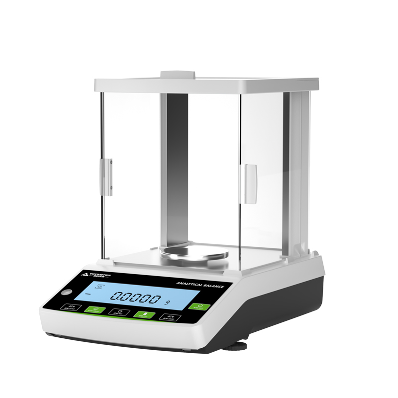
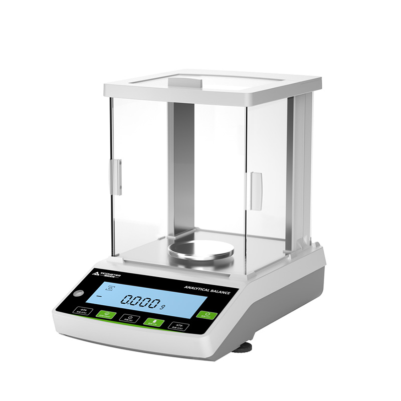
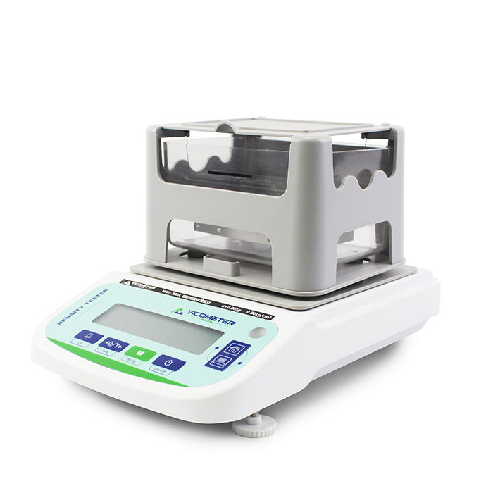
Recently, the Infrared Dew Point Indicator designed by VicoMeter (Jiangsu Victor Instrument Meter Co., Ltd.) was granted a national utility model patent, patent No. CN201720542103.X, and received the Utility Model Patent Certificate issued by the China National Intellectual Property Administration. This signifies VicoMeter's recognition in the field of utility model patents, deeper protection for its innovations, and a further enhancement of its overall competitiveness.
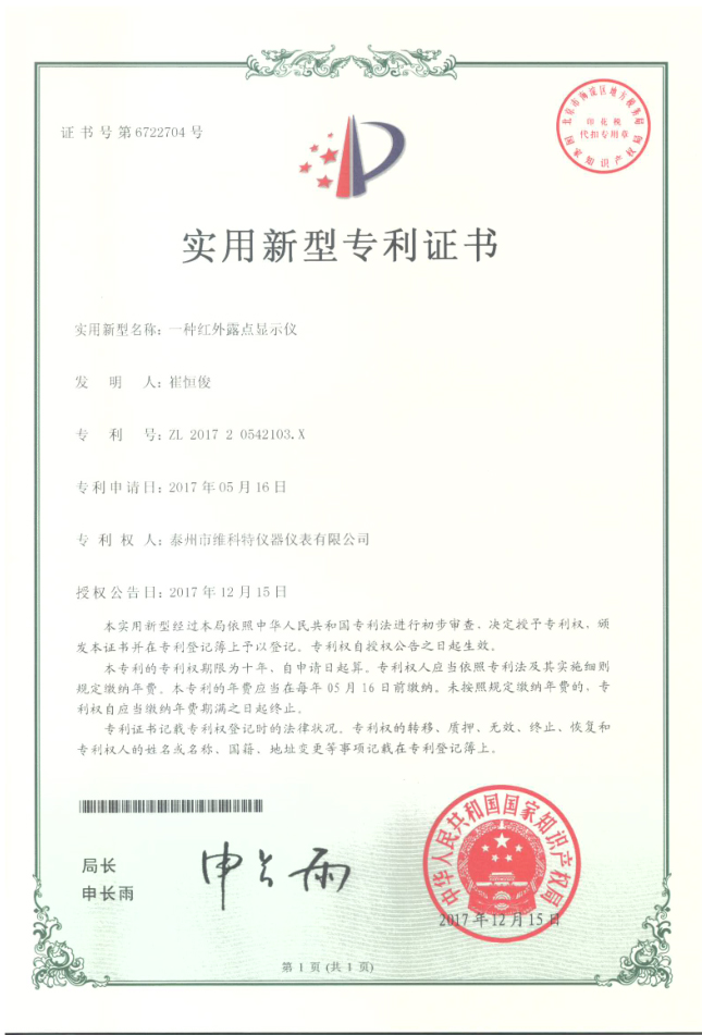
O certificado de patente é um documento legal emitido pelo departamento de administração de patentes do Conselho de Estado (ou seja, a Administração Nacional de Propriedade Intelectual da China) ao requerente da patente, após o pedido de patente ter sido examinado e considerado qualificado, sem que tenham sido encontrados fundamentos de recusa e com o cumprimento das condições para a concessão do direito de patente, juntamente com a decisão de conceder o direito de patente.
Os certificados de patente dividem-se em certificados de patente de invenção, certificados de patente de modelo de utilidade e certificados de patente de desenho industrial.
O modelo de utilidade é um dos três tipos de patente (invenção, modelo de utilidade e desenho industrial). O modelo de utilidade refere-se a uma nova solução técnica proposta para a forma, a estrutura ou a combinação destas em um produto, adequada ao uso prático. A Lei de Patentes estabelece requisitos de atividade inventiva e de nível técnico menores para os modelos de utilidade do que para as patentes de invenção, mas seu valor prático é grande.
Ao longo de anos de constituição, operação e aprimoramento, a VicoMeter aumentou efetivamente a consciência de propriedade intelectual de seus gestores e colaboradores, mobilizou o entusiasmo dos colaboradores para a invenção e a criação, integrou estreitamente os resultados de inovação tecnológica à propriedade intelectual e fortaleceu a competitividade central da empresa.
No futuro, a VicoMeter continuará a oferecer aos clientes produtos e serviços de qualidade e a dar a sua devida contribuição para a indústria de instrumentos analíticos da China — tornando os ensaios mais exatos, a operação mais simples e os usuários mais tranquilos.
O presente modelo de utilidade revela um indicador de ponto de orvalho infravermelho, que compreende um tubo de isolamento a vácuo, uma placa de cobertura e uma placa de fundo inferior. As duas extremidades do tubo de isolamento a vácuo estão fixadas, respectivamente, aos centros da placa de cobertura e da placa de fundo inferior. A placa de cobertura é dotada de um tubo de admissão em correspondência com o tubo de isolamento a vácuo, e a placa de cobertura é dotada de uma placa de fixação em correspondência com o tubo de admissão. Um tubo de fluxo está previsto no interior do tubo de isolamento a vácuo em correspondência com a extremidade do tubo de admissão, e a extremidade do tubo de fluxo está ligada a uma câmara de detecção. Uma placa de detecção está prevista na câmara de detecção, e a placa de detecção é dotada de um espelho côncavo em correspondência com a extremidade do tubo de fluxo. Um sensor de temperatura infravermelho está previsto no centro do espelho côncavo. O topo da câmara de detecção está ligado a um tubo de circulação, e a extremidade do tubo de circulação está em conexão comunicante com o tubo de fluxo. O indicador de ponto de orvalho infravermelho tem estrutura simples e operação prática, e melhora efetivamente a exatidão dos dados de detecção do ponto de orvalho de gases.
1. An infrared dew point indicator, comprising a vacuum insulated tube (1), a cover plate (2), and a lower bottom plate (3), characterized in that the two ends of the vacuum insulated tube (1) are fixedly connected to the centers of the cover plate (2) and the lower bottom plate (3) respectively; the cover plate (2) is provided with an intake pipe (21) corresponding to the vacuum insulated tube (1); the cover plate (2) is provided with a fixing plate (22) corresponding to the intake pipe (21); a flow tube (11) is provided inside the vacuum insulated tube (1) corresponding to the end of the intake pipe (21); the end of the flow tube (11) is connected to a detection chamber (12); a detection plate (121) is provided in the detection chamber (12); the detection plate (121) is provided with a concave mirror (13) corresponding to the end of the flow tube (11); an infrared temperature sensor (14) is provided at the center of the concave mirror (13); the top of the detection chamber (12) is connected to a circulation tube (122); and the end of the circulation tube (122) is in communicating connection with the flow tube (11).
2. The infrared dew point indicator according to claim 1, characterized in that the cover plate (2) is provided with an intake through hole (23) and an outlet through hole (24) at the two ends corresponding to the intake pipe (21) respectively, and both the intake through hole (23) and the outlet through hole (24) are in communicating connection with the interior of the vacuum insulated tube (1).
3. The infrared dew point indicator according to claim 1, characterized in that the intake end of the intake pipe (21) is provided with a one-way intake valve (211).
4. The infrared dew point indicator according to claim 1, characterized in that the flow tube (11) is arranged in a spiral shape.
5. The infrared dew point indicator according to claim 1, characterized in that the detection plate (121) is provided with a light source (131) around the periphery of the concave mirror (13).
6. The infrared dew point indicator according to claim 1, characterized in that the output end of the infrared temperature sensor (14) is connected to a display (141), and the display (141) is arranged on the cover plate (2).
Um indicador de ponto de orvalho infravermelho
Campo técnico
[0001] The present utility model relates to the technical field of dew point detection and display, and in particular to an infrared dew point indicator.
Contexto
[0002] Since oxygen and nitrogen are mainly filled into aircraft in the field, accurately measuring the dew point temperature of the gas before filling can not only improve the quality of flight support but also enhance flight safety. At present, most dew point meters on the market adopt semiconductor refrigeration, which consumes a large amount of electric energy and is therefore unsuitable for field use or outdoor conditions; moreover, repeated detection is not possible during testing, resulting in low accuracy of detection results. Summary
[0003] The purpose of the present utility model is to provide an infrared dew point indicator that addresses the shortcomings existing in the prior art.
[0004] To achieve the above purpose, the present utility model adopts the following technical solution:
[0005] An infrared dew point indicator comprises a vacuum insulated tube, a cover plate, and a lower bottom plate. The two ends of the vacuum insulated tube are fixedly connected to the centers of the cover plate and the lower bottom plate respectively. The cover plate is provided with an intake pipe corresponding to the vacuum insulated tube, and the cover plate is provided with a fixing plate corresponding to the intake pipe. A flow tube is provided inside the vacuum insulated tube corresponding to the end of the intake pipe, and the end of the flow tube is connected to a detection chamber. A detection plate is provided in the detection chamber, and the detection plate is provided with a concave mirror corresponding to the end of the flow tube. An infrared temperature sensor is provided at the center of the concave mirror. The top of the detection chamber is connected to a circulation tube, and the end of the circulation tube is in communicating connection with the flow tube.
[0006] Preferably, the cover plate is provided with an intake through hole and an outlet through hole at the two ends corresponding to the intake pipe respectively, and both the intake through hole and the outlet through hole are in communicating connection with the interior of the vacuum insulated tube, thereby improving the cooling efficiency inside the vacuum insulated tube.
[0007] Preferably, the intake end of the intake pipe is provided with a one-way intake valve. When gas is injected into the flow tube, the one-way intake valve effectively prevents gas leakage, improving the dew point detection accuracy of the device.
[0008] Preferably, the flow tube is arranged in a spiral shape, which increases the time the gas stays in the flow tube and improves the cooling effect on the gas in the flow tube.
[0009] Preferably, the detection plate is provided with a light source around the periphery of the concave mirror. When the gas in the flow tube is injected into the concave mirror, the light source shines light toward the concave mirror, and the light is repeatedly refracted inside the concave mirror to lower the temperature therein; when the temperature inside the concave mirror matches the temperature of the gas, the gas condenses into frost.
[0010] Preferably, the output end of the infrared temperature sensor is connected to a display, and the display is arranged on the cover plate. The infrared temperature sensor detects the temperature at which the gas condenses into frost inside the concave mirror to obtain the dew point data of the gas, and transmits the dew point data to the display.
[0011] In the present utility model, the gas to be detected is injected into the flow tube through the intake pipe, and the gas flows and is cooled inside the flow tube. The intake through hole and outlet through hole provided in the cover plate corresponding to the vacuum insulated tube circulate air through the vacuum insulated tube to carry away heat from within it. The gas in the flow tube enters the detection chamber, and after being pressurized, the gas in the detection chamber re-enters the flow tube through the circulation tube, improving the concentration effect of the gas in the detection chamber. The gas in the flow tube is injected into the concave mirror, the light source shines light toward the concave mirror, and the light is repeatedly refracted inside the concave mirror to lower the temperature therein; when the temperature inside the concave mirror matches the temperature of the gas, the gas condenses into frost. The infrared temperature sensor detects the temperature at which the gas condenses into frost inside the concave mirror to obtain the dew point data of the gas, and transmits the dew point data to the display. The infrared dew point indicator has a simple structure and convenient operation, and effectively improves the accuracy of gas dew point detection data.
Descrição dos desenhos
[0012] FIG. 1 is a schematic structural diagram of an infrared dew point indicator proposed by the present utility model;
[0013] FIG. 2 is a schematic structural diagram of part M of the infrared dew point indicator proposed by the present utility model;
[0014] FIG. 3 is an enlarged schematic structural diagram of part B of the infrared dew point indicator proposed by the present utility model.
[0015] In the figures: 1 vacuum insulated tube; 11 flow tube; 12 detection chamber; 121 detection plate; 122 circulation tube; 13 concave mirror; 131 light source; 14 infrared temperature sensor; 141 display; 2 cover plate; 21 intake pipe; 211 one-way intake valve; 22 fixing plate; 23 intake through hole; 24 outlet through hole; 3 lower bottom plate.
Implementação detalhada
[0016] The technical solutions in the embodiments of the present utility model are described clearly and completely below with reference to the accompanying drawings in the embodiments of the present utility model. Obviously, the described embodiments are only some of the embodiments of the present utility model, rather than all of them.
[0017] Referring to FIGS. 1-3, an infrared dew point indicator comprises a vacuum insulated tube 1, a cover plate 2, and a lower bottom plate 3. The two ends of the vacuum insulated tube 1 are fixedly connected to the centers of the cover plate 2 and the lower bottom plate 3 respectively. The cover plate 2 is provided with an intake pipe 21 corresponding to the vacuum insulated tube 1, and the intake end of the intake pipe 21 is provided with a one-way intake valve 211. When gas is injected into the flow tube 11, the one-way intake valve 211 effectively prevents gas leakage, improving the dew point detection accuracy of the device. The cover plate 2 is provided with a fixing plate 22 corresponding to the intake pipe 21, and the cover plate 2 is provided with an intake through hole 23 and an outlet through hole 24 at the two ends corresponding to the intake pipe 21 respectively; both the intake through hole 23 and the outlet through hole 24 are in communicating connection with the interior of the vacuum insulated tube 1, improving the cooling efficiency inside the vacuum insulated tube 1. A flow tube 11 is provided inside the vacuum insulated tube 1 corresponding to the end of the intake pipe 21, and the flow tube 11 is arranged in a spiral shape, which increases the time the gas stays in the flow tube 11 and improves the cooling effect on the gas in the flow tube 11. The end of the flow tube 11 is connected to a detection chamber 12, a detection plate 121 is provided in the detection chamber 12, and the detection plate 121 is provided with a concave mirror 13 corresponding to the end of the flow tube 11; the detection plate 121 is provided with a light source 131 around the periphery of the concave mirror 13. When the gas in the flow tube 11 is injected into the concave mirror 13, the light source 131 shines light toward the concave mirror 13, and the light is repeatedly refracted inside the concave mirror 13 to lower the temperature therein; when the temperature inside the concave mirror 13 matches the temperature of the gas, the gas condenses into frost. An infrared temperature sensor 14 is provided at the center of the concave mirror 13. The top of the detection chamber 12 is connected to a circulation tube 122, and the end of the circulation tube 122 is in communicating connection with the flow tube 11. The output end of the infrared temperature sensor 14 is connected to a display 141, and the display 141 is arranged on the cover plate 2. The infrared temperature sensor 14 detects the temperature at which the gas condenses into frost inside the concave mirror 13 to obtain the dew point data of the gas, and transmits the dew point data to the display 141.
[0018] In the present utility model, the gas to be detected is injected into the flow tube 11 through the intake pipe 21, and the gas flows and is cooled inside the flow tube 11. The intake through hole 23 and outlet through hole 24 provided in the cover plate 2 corresponding to the vacuum insulated tube 1 circulate air through the vacuum insulated tube 1 to carry away heat from within it. The gas in the flow tube 11 enters the detection chamber 12, and after being pressurized, the gas in the detection chamber 12 re-enters the flow tube 11 through the circulation tube 122, improving the concentration effect of the gas in the detection chamber 12. The gas in the flow tube 11 is injected into the concave mirror 13, the light source 131 shines light toward the concave mirror 13, and the light is repeatedly refracted inside the concave mirror 13 to lower the temperature therein; when the temperature inside the concave mirror 13 matches the temperature of the gas, the gas condenses into frost. The infrared temperature sensor 14 detects the temperature at which the gas condenses into frost inside the concave mirror 13 to obtain the dew point data of the gas, and transmits the dew point data to the display 141.
[0019] The above descriptions are merely preferred specific embodiments of the present utility model, but the scope of protection of the present utility model is not limited thereto. Any person skilled in the art who makes equivalent substitutions or modifications based on the technical solutions and the inventive concept of the present utility model within the technical scope disclosed herein shall be covered by the scope of protection of the present utility model.
Produtos vistos recentemente




Copyright © Jiangsu Victor Instrument Meter Co., Ltd. Todos os direitos reservados | Mapa do site | Suporte técnico: Centro de Operações VicoMeter